AFT Impulse Simplifies Design of Complicated Water Deluge System
AFT Impulse™ Case Study
Reynolds, Smith & Hills, Inc. | Sound Suppression System | Aerospace

“Being able to roll over the model [into AFT Impulse] from Fathom and
edit as necessary is a great time saver. Then setting up all of the
different scenarios and being able to take the results and produce graphs
of the transient system, all within one program saves time and effort.”
–William Allred, RS&H Mechanical Engineer
PROBLEM
- Water deluge system design for ISS rocket launch
- Water system would aid in sound suppression and launch pad cooling
ANALYSIS
- AFT Impulse modeled the hypothetical system design to determine flow rates and valve opening times
- Scenario manager allowed for “what if” scenarios
- Exported transient force data for CAESAR II, pipe stress analysis
SOLUTION
- Determined the system could meet the flow design requirements with proper pipe sizing, nozzle sizing, and valve opening times
- Client now has a functional model for future analysis
Ready to try AFT Impulse?
Problem Explained
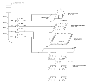
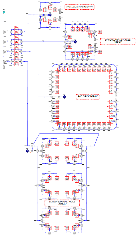
William Allred, mechanical engineering associate at Reynolds, Smith & Hills, Inc. (RS&H), used AFT Impulse to design a complicated four level Water Deluge System (241 pipes, 238 junctions, 100 deluge nozzles and eight subsystem valves) to meet flow and timing requirements set in a fictitious situation. Although the details pertaining to the client, rocket, launch pad location and flow requirements were fabricated, RS&H used realistic design methods to size pipes and valves, balance the system and accurately determine valve opening times to meet or exceed flow requirements.
In the created scenario, Allred had to complete a water deluge system design for Launch Pad XB for a company called Rocket-Tech. The launch pad was set in Brevard County, Florida and was host to a small class liquid fueled rocket called SRC-3. The rocket’s job was to transport crucial payloads to the International Space Station (ISS). Since this rocket was to be utilized far more frequently than any other commercial vehicle, and would take more trips to the ISS, local area representatives demanded minimal noise from the frequent launches.
Tools & Analysis
The water design system created for this setup was meant to provide sound suppression from the rocket blast by providing water to the launch pad and exhaust holes at specific flow rates, and therefore was of great importance. The design also provided cooling for the pad surface from the high temperature exhaust plume it would be subjected to during each launch.
During the design process, AFT Impulse was crucial in a number of ways. The sectioned pipe method feature was used to increase the shortest pipe length from 2 to 4 feet (.6 to 1.2 meters). This reduced the pipe friction by half, which provided the same friction drop results. This reduced the model run time and made the iterative design process more efficient (see Figure 2).
The Scenario Manager feature in AFT Impulse was also found to be helpful for the engineers. The model was built using the “Base Scenario” with a short model run time. This gave designers an idea of how each subsystem behaved in a quick manner. A child scenario was created from the base scenario and was used to decide valve opening times for each subsystem, as well as to observe the results from the full launch window. By creating children scenarios and applying the “Ignore Transient Data” feature to simulate a valve failing to open, they were able to show their client what happens when a valve failure occurs independently in each system (see Figure 3 – summary of flow requirements and valve failure results).
Solutions & Benefits
AFT Impulse is compatible with another software program called Caesar II, which allowed designers to export data to the program and observe pipe stresses and change the pipe supports accordingly.
“Manual calculations on a complex piping system would be very difficult,” said Allred, when considering the benefits of AFT Impulse. “Using AFT Impulse relieves designers of this burden and allows any number of ‘what if’ scenarios to be analyzed. This can help in determining if the three main-focus areas of the design meet system requirements: pipe sizing, nozzle sizing, and valve-open timing. Once the model is complete and results are obtained, the benefits don’t stop there. The client then has a fully functional model of their water deluge system, which can be used to verify the system’s capability to be used with other vehicles’ requirements, or to show what system requirements may be needed if vehicle requirements are not met.”


