Simulation of Transfer and Distribution of Thermally Hydrolyzed Sludge with AFT Fathom
AFT Fathom™ Case Study
Jacobs CH2M | Thermally Hydrolyzed Sludge | Water & Wastewater

“A key to proving the operation concept for this
system was being able to model with three different
non-Newtonian fluids”
– Dan Robillard, Mechanical Engineer
PROBLEM
- Expansion of wastewater facility to include thermal hydrolysis system and five digester units
- Non-Newtonian nature of multiple system fluids, incorporating different rheology for each
ANALYSIS
- AFT Fathom was used to model Power Law non-Newtonian fluids
- Control structure was modeled to control flow to parallel digester units
SOLUTION
- Piping, pumps, and control valves for the digester feed and cooling system were adequately sized
Ready to try AFT Fathom?
Problem Explained
Dan Robillard, a Mechanical Engineer with Jacobs CH2M, successfully used AFT Fathom™ to model and simulate the transfer and distribution of thermally hydrolyzed sludge (THS) to digesters at a San Francisco, California, USA area wastewater plant. This project reflects an expansion where a thermal hydrolysis system and five digesters were being added on to the existing plant.
The goal was to provide sizing calculations for the piping, pumps, and control valves for the digester feed and cooling system. AFT Fathom was successfully used to model a system which processes and combines two sludges: a thermally hydrolyzed sludge (THS) which was diluted before being combined with a digester sludge (DS).
The sludges have different rheology but were all modeled as Power Law non-Newtonian fluids. A key to proving the operation concept for this system was being able to model with three different non Newtonian fluids, with one of them being regulated with flow control valves to ensure an even split between the four operating digesters.
Tools & Analysis
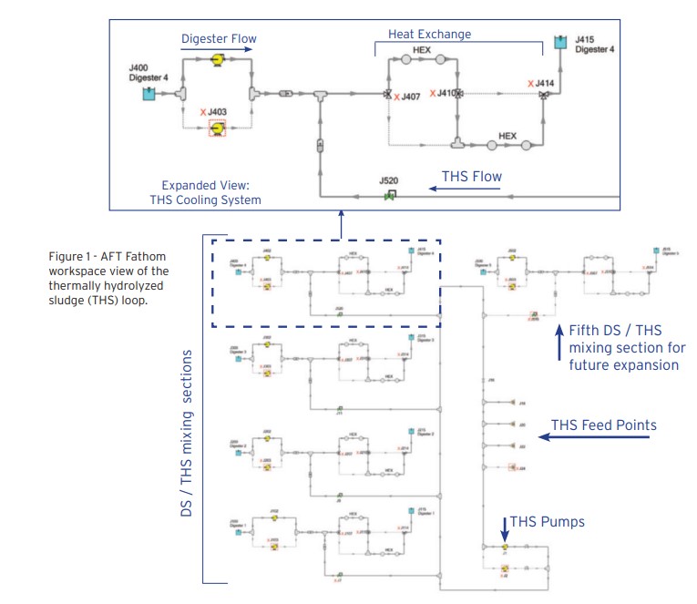
THS from flash tanks is diluted with water to a total solids (TS) concentration of approximately 10% and then pumped to a THS loop and heated to a minimum temperature of 165°F (74°C). Variable-speed pumps adjust to maintain a flow rate between 120-130 gpm (27-30 m3/ hr) in each section of pipeline between the THS take-off to each digester as well as between the THS feed point from the flash tanks. A flow meter measures the flow and maintains a velocity of 3 ft/s (1 m/s) to keep solids from settling out and prevent THS from solidifying in the pipeline.
Each primary digester has a single feed line that branches off from the THS loop. A pneumatically operated flow control valve evenly divides the flow to each digester under normal operating conditions. One flow control valve is designated as the most open valve and remains at a designated percent open set point.
Solutions & Benefits
The other flow control valves will adjust as needed to maintain their flow control set points while evenly distributing the flow.
The digested sludge (DS) is conveyed from each digester using adjustable-speed cooling heat exchanger (HEX) pumps. DS is mixed with THS and then flow to a set of heat exchangers to cool the sludge mixture.
As the incoming THS flow rate varies, the pumps vary their speed to maintain a set flow rate of 380 gpm (86 m3/hr) through the HEXs. See Detail in Figure 1. AFT began incorporating non-Newtonian fluids into software products in the late 1990’s, primarily due to a specific request from (formerly) CH2M Hill. We are proud to see these features come full-circle in case studies such as this. We are honored to contribute any way we can to help build city infrastructure around the world.

