AFT Fathom Results Agree With Power Plant Field Data – Temperature Control Problem Resolved
AFT Fathom™ Case Study
Ameren Missouri | Circulating Water System | Power Generation

“Accurate modeling of expected system pressure,
pressure drop, valve Cv and resulting valve position was critical”
– Stephen Williams, Consulting Engineer
PROBLEM
- Over 45 years of heat exchanger fouling led to poor temperature control
- Large losses due to scaling forced control valves to operate at or near full open condition
ANALYSIS
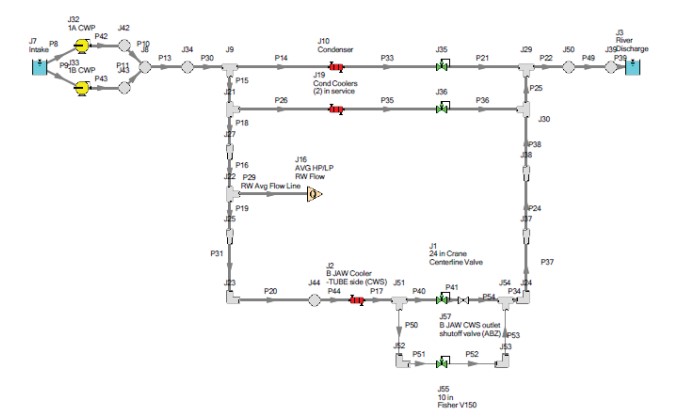
- An AFT Fathom model was built and calibrated to the system to size new heat exchangers and control valves
- A single control valve was unable to cover the desired control range
SOLUTION
- Combinations of control valves were considered
- A parallel control valve system with a small and large valve to control low and high flow respectively was developed
Ready to try AFT Fathom?
Problem Explained
Stephen Williams, consulting engineer at Ameren Missouri, used AFT Fathom to model a circulating water system at the Sioux Power Plant, a supercritical coalfired power plant located near St. Louis. The system is a high-flow, low-pressure system that provides cooling water.
Temperature control of the existing system was problematic. The heat exchangers had become extremely fouled over ~45 years of service and had lost significant heat transfer capability. Due to this loss, control valves typically operated at or near full open condition. New heat exchangers were needed to restore the heat transfer capability of the system and new control valves must be able to reliably regulate temperature across the range of expected operating conditions.
Tools & Analysis
A Fathom model was constructed to test valve performance based on the manufacturer’s published Cv data. The expected design and winter minimum flow rates are 6,840 gpm (1,550 m3/h) and 1,390 gpm (316 m3/h), respectively. For the model, these flow rates were “hard coded” in the control valve properties screen.
Very few valves were available that would fit in the existing piping configuration. Multiple models were constructed and verified that a single valve would not work. Large valves did not have sufficient turndown to accurately control the low end flow, while smaller valves would fail to achieve full flow at fully open conditions. A 24 inch (61 cm) valve would have to be used for the high end of the flow range and a smaller valve for the low range flows.
Solutions & Benefits
Based on the model results, a parallel valve arrangement was selected using a 10-inch (25.4 cm) Fisher V150 V notch control valve in parallel to the 24-inch butterfly valve. The control logic was setup such that the 24-inch valve would be used above 20% open, and the 10 inch V notch valve would be used for flows below. Fathom determined the control cutover point to be at 3,500 gpm (800 m3/h).
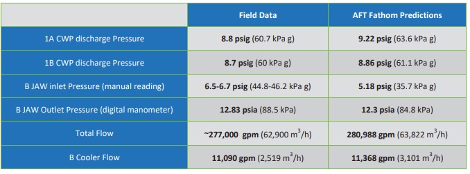
To validate model performance, field data was collected and compared to the model data.
“Fathom allowed the engineer to model multiple valve selections and configurations to determine what control scheme would provide best temperature control over the range of flows and resultant pressure drops. Since this is a high flow, low-pressure system, accurate modeling of expected system pressure, pressure drop, Valve Cv and resulting valve position was critical.”

