Dangerous Petrochemical Loading Surge Avoided with AFT Impulse Analysis
AFT Impulse™ Case Study
Ingenero Technologies | Pipeline | Chemical & Petrochemical

“The model’s predicted surge of 10 barg (140 psig) matched the
worst-case operating data after implementing recommendations.”
-Swapnil Paingankar, Mathematics Modeling Specialist
PROBLEM
- Pressures in excess of 13.2 barg (191 psig) generated at end of loading process
- Noise and vibration due to surge and chattering check valves caused concern
ANALYSIS
- Determined control valve closure was cause of surge event
- AFT Impulse model calibrated closure to match measured excess pressure
SOLUTION
- Determined new valve closure strategy to mitigate surge
- Comparisons to post-implementation data kept surge below acceptable level, as expected
Ready to try AFT Impulse?
Problem Explained
Ingenero Technologies engineers Mohommed Ilyas Mullani and Swapnil Paingankar were tasked with analyzing a petrochemical transfer line issue causing a hazard during truck loading. Ingenero’s client experienced sudden pressure surge near the end of the truck loading process, generating pressures in excess of 13.2 barg (191 psig). This pressure surge caused vibration and loud noise during the event, in part due to chattering relief valves downstream of the pumps. Since a loading operation would occur once or twice per month, the client requested a root cause analysis on the pressure surge to determine a mitigation strategy.
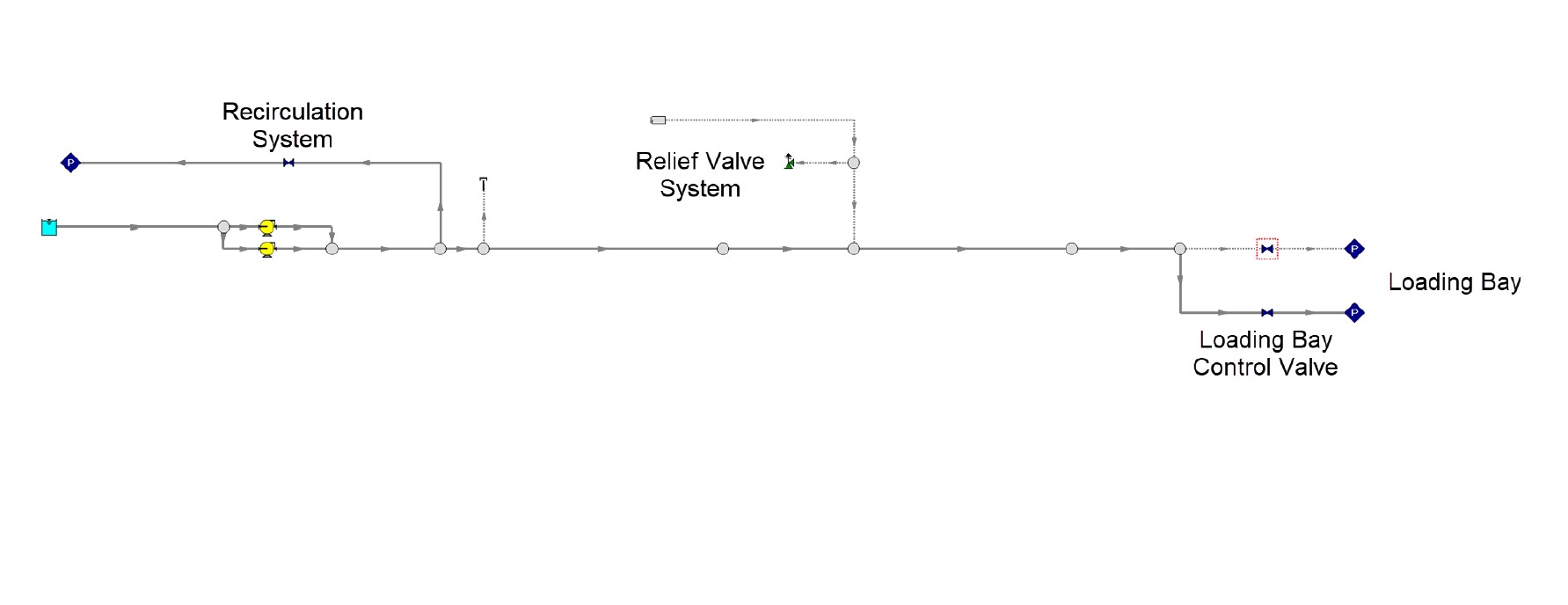
The truck loading system consists of two tanks with individual pumps and transfer lines. Downstream of each pump are two lines for recirculation and relief purposes, both redirecting flow back to their respective tanks. During a loading operation, a control valve at the truck loading bay would close as the truck fills, reducing flow. As flow reduced, the controlled recirculation valve would open to avoid stressed pump operation. The relief valves opened and chattered during the operation as a result of the unexpected surge. While the pump’s relief valves opened during the loading event, they were not intended for use during normal operation. Since most loading occurs through one tank, the AFT Impulse model was simplified as found in Figure 1.
Tools & Analysis
The model was built based on P&IDs, datasheets, pump performance curves, isometric drawings as well as fluid properties provided by the client. Operational data from the plant was instrumental to calibrating the system for transient analysis. In this case the Ingenero engineers were limited in their data, with only two steady state operating cases to tune the model. Regardless, the model was calibrated to within 10% of each steady state data set in anticipation of transient analysis.
Mullani and Paingankar had two areas of concern during loading. First was determining if the recirculation system was working as intended to provide an alternate flow path. While operational data indicated the recirculation system reacted late, testing a loading operation with full continuous recirculation did not mitigate the surge event. That reasonably eliminated poor recirculation as the cause of surge.
This left Mullani and Paingankar’s other concern, the closure of the loading bay control valve, as the surge suspect. The engineers again ran into obstacles with a limited operational data set to model the transient valve closure.
Solutions & Benefits
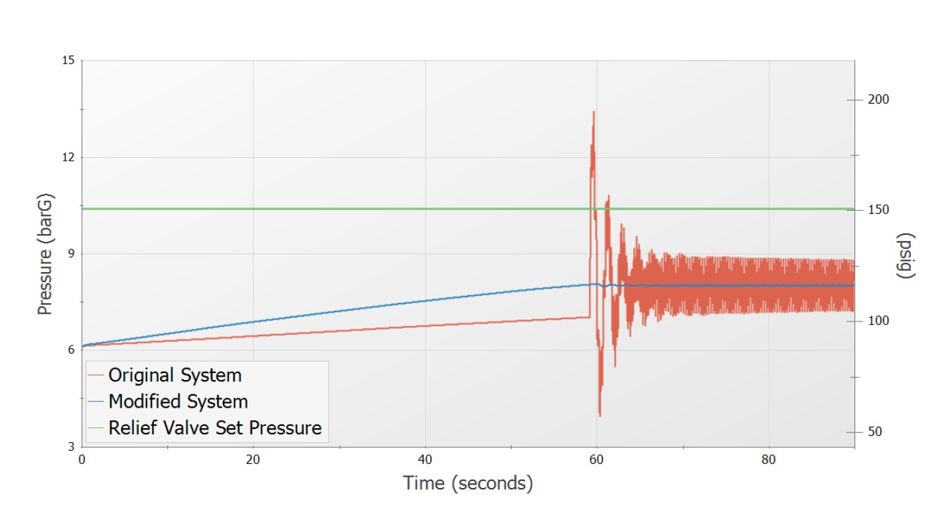
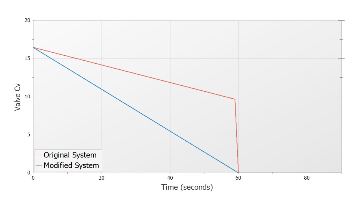
In their testing they developed a valve closure pattern as found in Figure 2, which produced a pressure spike consistent with the measured 13.2 barg (191 psig).
The surge event was addressed by the Ingenero engineers by adjusting the loading control valve behavior (shown for comparison in Figure 2) which kept the surge pressure reasonable and below the relief valve set point. The recirculation issue was also addressed with improved measurement and control valve behavior.
After the team’s recommendations were implemented, the loading surge was significantly reduced and the vibration and noise issues were avoided. The client was able to provide a post-recommendation data set during a worst-case loading operation with flow from both tanks simultaneously. The resulting 10 barg (140 psig) surge matched AFT Impulse results for a similar operation, further reaffirming the team’s confidence in the accuracy of their model.


