Experimental Helium Cooling Loop for Nuclear Fusion Testing Modeled in AFT Arrow
AFT Arrow™ Case Study
Vertex Piping Engineers | Heat Transfer | Nuclear

“Modeling the closed loop thermo-hydraulics of the system
was a challenging task”
– Tejas Ambre and Dr. S. Bharath, Vertex Piping Engineers
PROBLEM
- ITER nuclear fusion research project required component testing
- Losses of compressible Helium cooling fluid impacted by tightly-coupled thermo-hydraulics
ANALYSIS
- Built AFT Arrow model of turbo-circulators, economizer, and various heat exchangers
- Modeled bypasses to achieve different test temperatures
SOLUTION
- Determined operational range based on turbo-circulator capacity
- Found their initial insulation bid did not meet safety requirements
Ready to try AFT Impulse?
Problem Explained
While nuclear fusion has not yet been proven as a self-sustaining source of energy, many efforts have been made to design its supporting systems in anticipation of its development. ITER is the largest international research and engineering project to prove the viability of nuclear fusion, with its planned successor DEMO outlining the transition of the technology to electricity generation. As with traditional nuclear reactions, managing the heat generated in the nuclear fusion process is essential.
Tejas Ambre and Dr. S. Bharath with Vertex Piping Engineers, working with ITER, was granted a project to engineer, fabricate, and commission an experimental helium cooling loop. This cooling loop will be used to evaluate different components of the ITER project, including the Indian Test Blanket Module, fusion blanket wall mock-ups, Pb-Li heat exchangers, and other fusion blanket components. Due to the compressible nature of helium, the team modeled the system in AFT Arrow to determine its allowable operating conditions.
Tools and Analysis
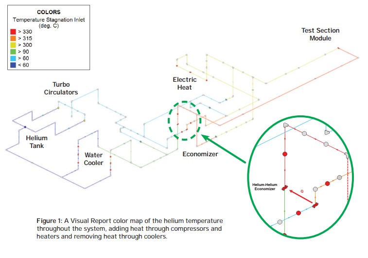
The helium cooling system itself is made of up 6 major components. The first component is a turbo-circulator with a variable frequency drive, used to compress helium and provide flow. The compressed helium is fed to a helium-helium economizer to pre-heat the gas, followed by an electric heater. The helium is then fed to the tested component where the gas removes heat. This collected heat is transferred through the economizer from hot to cold before the gas is cooled by helium-water heat exchangers, completing the loop. Throughout the cooling system are several control valve bypasses to further control mixing and delivery temperature for different cases. Figure 1 displays a labeled diagram, including a color map of the gas’ temperature through the process.
The helium cooling system had many important design requirements. Since the system would be used for testing fusion blank components, the team had to determine the allowable range of flowrates provided by the turbo-circulator at its different speeds. The team similarly had to ensure the designs fell within their rated cooling capacity, maximum velocity limits, and allowable delivery temperature specifications at different points in the loop. The different design cases were managed in AFT Arrow’s Scenario Manager, ensuring all design variations and changes were captured in a single file.
Solutions & Benefits
Heat transfer analysis was essential since the team was designing a cooling system. The team was able to model the ambient pipe heat losses through AFT Arrow’s builti-n internal and external heat transfer correlations, as well as determine the insulation thickness to meet their 60°C (140°F) surface temperature safety requirement. Figure 2 compares their initially bid 50 mm insulation to the final 200 mm insulation.
The team also modeled the Helium-Helium economizer, which recycles energy from the hot side of the cooling loop to the cool side to reduce the overall heat duty. Using heat transfer principles, the team was able to simplify their analysis with exchanger outlet temperature specifications to improve the convergence of their model. In all cases, the energy balance was met throughout their economizer design.
It is clear the team at Vertex was able to model the tightly coupled thermo-hydraulics of their closed loop system with AFT Arrow. The team was able to model the mechanical controls, heat exchangers, hot/cold loop interactions, and manage the capacity requirements of their equipment throughout their many cases. While nuclear fusion may be years if not decades away, teams like those at Vertex and tools like AFT Arrow are essential to nuclear fusion’s immediate success.

