Data Center Air Cooling System Conversion Project Validated Using AFT Fathom
AFT Fathom™ Case Study
Swanson Rink | Data Center Air Cooling | General Facility

“This analysis would have been nearly impossible using hand
calculation methods. The ability to have the control valves balance
24 branches simultaneously was great.”
– Rory Heim, Mechanical Engineer
PROBLEM
- Use existing HVAC system for converting an office building into a data center
- But heating and air flow requirements are much lower than the original system design – oversized ductwork
ANALYSIS
- AFT Fathom was used to model the existing system to see the previous flow distribution
- They modeled the system with dampers on each branch to meet new flow requirements
SOLUTION
- The existing HVAC system could meet the decreased demand of air flow, despite the oversized ducting
- The dampers can change position to meet other flows as demand changes over time
Ready to try AFT Fathom?
Problem Explained
Swanson Rink developed a master plan for converting a high-rise office building into a multiuser, data center space. The client wished to use as much of the existing air conditioning system as possible, and the vertical duct system needed to be reused to make the project financially viable. The challenge was that the heating and air flow requirements were much lower for the new data center compared to the previous office space configuration.
There were two identical vertical duct systems on the north and south of the building. Each original duct system was designed for ~200,000 CFM (ft3/min), (5700 m3/min), and had pneumatic balancing dampers at two branches to each floor. The duct system serves 12 floors, for a total of 24 branches from the main duct.
The new south air handling unit (AHU), on which the model is based, was only 35,000 CFM (1000 m3/min), and the demand will slowly diminish as the building progresses in the master plan from air conditioning for office space to ventilation for data center space. The goal was to determine how to balance the new airflow requirements to each floor using the existing oversized ductwork at design conditions and as the load decreased over time.
Tools & Analysis
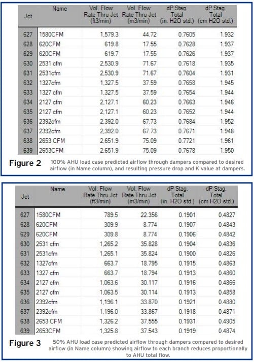
Rory Heim used AFT Fathom to determine the amount of static pressure the AHU fan required. Heim used fitting and losses in the ducts to keep the model clean with minimal junctions. He also named each valve with the CFM value, which allowed him to compare the desired CFM to the computed flow.
The plan was for the AHU to be installed and balanced using the existing branch takeoff dampers. One of the concerns was the AHU flow rate dropped when load was picked up by other systems. The air would take the path of least resistance to the closest dampers, and the furthest run would be starved unless the system was rebalanced.
Heim used control valves and regular valves to represent the dampers. Once the system ran correctly, he recorded the “K” values. He created a child scenario, and systematically replaced each control valve with a standard valve with the appropriate “K” value so each branch received the same flow as in the control valve scenario. He was able to lower the total flow rate of the system and explore where the air went during reduced flow.
Due to the existing duct system being vastly oversized for the needed air volume, there was negligible pressure drop associated with the main duct, and the air in each branch decreased proportionally to the decrease in total flow rate.
Solutions & Benefits
When asked about the benefits of modeling the system with AFT software, Heim said, “This analysis would have been nearly impossible using hand calculation methods. The ability to have the control valves balance 24 branches simultaneously was great.” Performing the same analysis by hand would have required simultaneous solving of 24 equations, followed by using equations to find the loss factor (K value) of each of the 24 control valves.
The ability to include junctions and fittings in the duct was very useful in keeping the presentation of the model simple and clear. Each valve was named with the desired CFM value, allowing quick comparison in the Output tab between desired CFM (shown in the “Name” columns) and actual CFM (shown in the “Vol. Flow” columns) (see Figures 2 & 3).

