Emissions Reduced at Commercial Power Plant Using AFT Arrow
AFT Arrow™ Case Study
Kiewit Engineering Group Inc. | Auxiliary Steam System | Power Generation

“The benefits of using AFT Arrow for this project were numerous.
The complexity of the flow-paths and nature of compressible
flow made the calculations near impossible to do in a timely
manner by hand.”
-Ryan Mathes, Mechanical Engineer
PROBLEM
- Emission regulations required power plant to change their exhaust process
- This change introduced damaging acid precipitation when in cold weather
ANALYSIS
- AFT Arrow was used to analyze existing steam system
- Effects of a new glycol heater to heat the exhaust was tested
SOLUTION
- Model reported sonic choking was present
- A larger pipe size was required to meet the new system demand
Ready to try AFT Impulse?
Problem Explained
Kiewit Engineering Group studies an existing auxiliary steam system for a commercial power plant to determine if an old glycol heating system was reactivated, if the existing header and steam letdowns were capable of supplying the glycol system in addition to other future users and current worst-case demands.
The steam system spans four aging coal boilers. During the cold winters in the 1970s, the plant utilized a glycol heating system that provided energy to the boiler stacks. The glycol (antifreeze) would heat the incoming exhaust gas. Later improvements to the boiler made this system obsolete, and it was partially removed and partially abandoned-in-place.
More recent emissions regulations have driven the plant to utilize a system that cuts down emissions, but results in the formation of acids that precipitate during cold weather startup and damage the air preheater. Kiewit’s customer desired to reactivate the glycol system to alleviate the issue; the idea is the exhaust gas is heated far enough above the acid-gas dew point that when it enters the air preheater to exchange heat with the incoming cold air, it does not drop down below the acid dew point.
Tools and Analysis
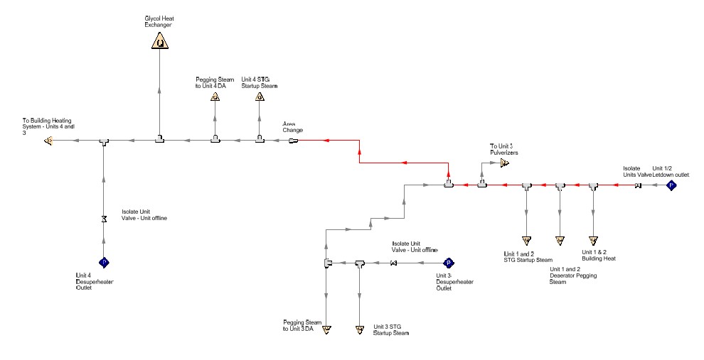
The goal of the model was to determine which letdowns would need to be increased in size to allow for more steam flow to the auxiliary steam system. Kiewit decided each letdown would be represented by an assigned pressure junction that would allow the necessary amount of steam flow at the set outlet pressure (150psig / 10 bar-g) so the maximum required steam flow through each letdown could be determined.
To construct an AFT Arrow™ model, Kiewit utilized the existing auxiliary steam Piping and Instrumentation Diagrams (P&IDs), newly-routed steam supply piping to the steam-glycol heat exchanger, and estimated future takeoffs for steam turbine.
Kiewit used the AFT Arrow Scenario Manager to run various simulations to analyze different conditions. A base scenario represented the as-designed system. Child scenarios were created to reflect variations in Unit configurations, steam supplies, etc. Some scenarios increased the size of the crosstie to 10” (25 cm) and they re-ran restricted scenarios where either the steam velocity is too high or there is choked flow.
Solutions & Benefits
It was determined a 10” (25 cm) crosstie would be sufficient, provided each steam letdown was sufficiently upgraded.
The AFT Arrow model allowed the Owner to confidently make a call to replace the 6” (15 cm) crosstie piping.
Additionally, this upgrade improves the reliability and operability of the system for current and future upgrades that will further enhance the startup speed of the facility and assist in meeting emissions requirements.
Ryan Mathes, a Kiewit Mechanical Engineer, said the benefits of using AFT Arrow for this project were numerous, “The complexity of the flow-paths and nature of compressible flow made the calculations near impossible to do in a timely manner by hand. The use of AFT Arrow saved both time and money for the Owner with respect to modeling and study hours. This allowed the Owner to utilize funding on other aspects of this work such as pipe routing and pipe support work.”
Kiewit worked with engineering and design support for this project and anticipates the upgraded model will be validated against online steam measurements once available.
